 The E & E Bay
Contents
Introduction
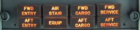
OK so you have seen the EQUIP caption & know roughly where the hatch is, but you are still curious to see what is inside. If you are going to attempt a peek in here away from this site then I recommend that you get an engineer to show you how to open, and more importantly, close the hatch, it is not straightforward.
There are actually 2 hatches which trigger the EQUIP light. The electronic equipment compartment located aft of the nose wheel well and the forward equipment compartment located forward of the nose wheel well. Most of the equipment is in the electronic equipment compartment. Also in the electronic equip compartment is the forward airstair door mechanism. The jackscrew is for the extension and retraction of the airstairs. The normal and standby motors are in the green housings at the base of the jackscrew.

All of the information, photographs & schematics from this website and much more is now available in a 374 page printed book or in electronic format.
*** Updated 05 Aug 2023 ***
![]()
![]()
![]()