 737 Nose Wheel
Home > Tech Photos > Walkaround > Nosewheel
Contents
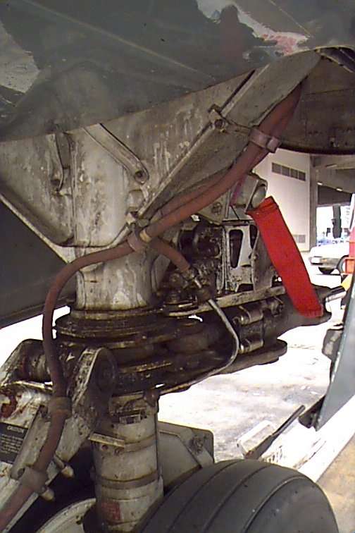
Ref: Top photograph:
Check lines for condition and leaks. The line to the left is the power for the taxi light, the line behind is for the downlock sensors.
The red pendant is attached to the steering bypass pin and should be fitted by the groundcrew with the tow bar for pushback. The system A hydraulic pumps should remain OFF until this has been confirmed either visually on the walkaround or over the interphone.
Ref: Bottom photograph:
The NG's have a lever on the front of the nose gear which is pulled up to insert the steering bypass pin. With age these levers are not returning to the vertical after the bypass pin is removed after pushback. The first you will know about it is when you find you do not have any nosewheel steering !!!

All of the information, photographs & schematics from this website and much more is now available in a 374 page printed book or in electronic format.
*** Updated 05 Aug 2023 ***
![]()
![]()
![]()