The NG's have 6 Display Units (DU's), these display the flight
instruments; navigation, engine and some system displays. They are
controlled by 2 computers - Display Electronics Units (DEU's).
Normally DEU 1 controls the Captains and the Upper DU's whilst DEU 2 controls the F/O's and the lower DU's. The whole
system together is known as the Common Display System (CDS).
The DU's normally display the PFD's outboard, ND's inboard, engine primary
display centre (upper) and engine secondary display lower. Although they can
be switched around into almost any other configuration with the DU selector
(shown left).
The CDS FAULT annunciation will only occur on the ground prior to the second
engine start, it is probably a DEU failure but is in any case a no-go item.
If a DEU fails in-flight, the remaining DEU will automatically power all 6
DU's and a DSPLY SOURCE annunciation will appear on both PFD's. The nomenclature requirements for these annunciations were
developed by Boeing Flight Deck
Crew Operations engineers during the early design phase of the 737NG
program. The intent of
the design function is as follows: · The CDS FAULT message is intended to be activated on ground to tell the
maintenance crew or air crew that the airplane is in a non-dispatchable
condition. · The DISPLAY SOURCE message is annunciated in air to tell the crew that
all the primary display information is from one source and should be
compared with all other data sources (standby instruments, raw data, etc.) to
validate its accuracy. Since the DISPLAY SOURCE message is intended to be activated in air and
CDS FAULT is
intended to be activated on ground, air/ground logic is used by CDS to
determine which
message is appropriate. The air/ground logic system uses a number of
inputs to determine
airplane state. One of the inputs used is “engines running”. CDS uses
the “engines running”
logic as the primary trigger for changing the CDS FAULT message to its
in-air counterpart. The
“engines running” logic is used in case the air/ground data isn't
correct as a result of other
air/ground sensing faults.
The DISPLAYS
- SOURCE selector is only used on the ground for maintenance purposes (to make
all 6 DU's be powered by either DEU 1 or 2). This may be why the switch is a
different shape to the other three; if not, it is still a good way to
remember that this is a switch that pilots should not touch!
Instrument transfer switches - NG
The DISPLAYS CONTROL PANEL annunciation merely indicates that an EFIS
control panel has failed. There is
an additional, rather bizarre, attention getter because the altimeter will
blank on the failed side, with an ALT flag, until the DISPLAYS - CONTROL PANEL switch
is positioned to the good side. Note that this is not the same as the EFI
switch on the -3/4/500's which was used to switch symbol generators.
EFIS Control Panel - NG
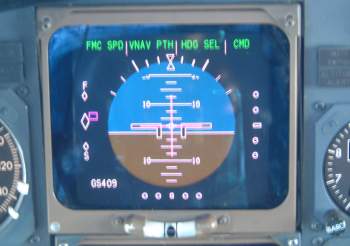
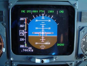
PFD - Primary Flight Display - NG
The speed tape shows minimum and maximum operating speeds. The maximum
operating speed provides a 0.3g manouvre margin to high speed buffet. The
minimum operating speed is computed from the SMYD as follows: The SMYD has
two flavours of Min manouvre speed. The first is identified as Vmnvr, the second as Vbl (low speed buffet). The transition from Vmnvr to Vbl
is dependent on gross weight, but in general Vmnver is output below 22,000 feet and
Vbl above that altitude.
Although not used directly in the calculation of Vmnvr, once the
airplane starts flying, gross weight becomes a factor indirectly (in the calculation of Vmnvr) via the load factor calculation.
FMC Gross Weight is used by the SMYD in the switching logic from Vmnvr
(min man speed) to Vbl.
One of the many customer PFD options is an analogue/digital angle of attack
display. The red line is the angle for stick shaker activation, the green
band is the range of approach AoA.
CDS Block Points
The 737NG Common Display System has had several software updates to
incorporate additional features, improvements to existing features and bug
fixes. Each new update is known as a Block Point. There have been six updates from BP98 to BP15. The latest software is BP 15, introduced in Oct 2016, fitted as standard from L/N 6119 onwards and to earlier aircraft by retrofit. A list of
each of their features is given in the book.
New Approach Formats
With increased navigational accuracy available and hardware/software
improvements on the 737, many new types of approaches have been developed. Cat
IIIb, LNAV/VNAV, RNAV(GPS), RNAV(RNP), IAN, GLS.
Cat IIIB ILS
documented as "Fail-Operational", is very similar to the current ILS display except that rollout guidance will display as "ROLLOUT" (armed) underneath the VOR/LOC annunciation. Fail-Operational aircraft have an extra MFD button “C/R” (Clear/Recall) to display system messages on the upper display unit. These messages can be either "NO LAND 3" or "NO AUTOLAND". Note Cat IIIa is still possible with a NO LAND 3 advisory. In this case green "LAND 2" annunciations will appear on both outboard display units.
LNAV/VNAV most non-precision approaches which are in the FMC database
may be flown to MDA in LNAV/VNAV. Look for the coded GP angle in the LEGS pages.
NPS (Navigation Performance scales) combine the display of ANP/RNP with LNAV/VNAV deviation to give either a Cat I approach of its
own or a transition to an approach. Note: NPS provides crew awareness of
airplane position with respect to the intended path and RNP. They are not
required for VNAV approaches, which may be flown with standard displays.
IAN (Integrated Approach Navigation) gives an ILS look-alike display
and allows the pilot to fly the approach like an ILS, ie by selecting APP on the
MCP. It is a Cat I only approach system which uses the FMC to transmit IAN
deviations to the autopilot and display system. Flight path guidance is from
navigation radios, FMC or a combination of both. The type of approach must first
be selected in the FMC. The flight mode annunciations will vary depending upon
the source of the navigation guidance as follows:
Approach
FMA
Localiser
based
approaches:
IGS
VOR/LOC
&
G/S
ILS
with G/S out, LOC, LDA, SDF
VOR/LOC
&
G/P
B/C LOC
BCRS &
G/P
If
FMC
is
used
for
course
guidance:
GPS,
RNAV
FAC
&
G/P
VOR,
NDB,
TACAN
FAC
&
G/P
Where FAC = Final Approach Course and G/P = Glidepath.
GNSS Landing System (GLS) Approaches use GPS and a ground based augmentation
system (GBAS) to give signals similar to ILS signals and will probably replace
ILS in the future. Certified May 2005, it is initially Cat I but will become Cat
IIIB and should have the capability for curved approaches.
Most of the above approaches require FMC U10.5+, CDS BP02+, FCC -709+ and
DFDAU & EGPWS.
The first 737-300's were not fitted with EFIS and the flight
instruments were almost identical to the 737-200Adv. The yellow warning lights
above the ADI are the instrument comparator warnings. The FMA annunciations were
all contained in the panel above the ASI
Non-EFIS FMA
The big Gotcha with SP-177 equipped 737-200Advs and non-EFIS Classics were the HSI source selectors, sometimes referred to as “Killer Switches”. These were located either side of the MCP and changed the HSI to show deviation either from the LNAV or ILS/VOR track. It is vitally important that these switches are set to VOR/ILS before commencing an approach otherwise you will still be indicating LNAV deviation rather than LLZ deviation.
HSI source selector switch
The standard Classics had no way to display metric altitude, which is used in some countries such as Russia and China. An optional digital metric altimeter could be fitted which was usually located below the VSI. The NG and MAX can display metric altitude by selecting MTRS on the EFIS control panel.
Metric Altimeter
The 737-300's were soon available with
EFIS, an option which most operators took. The EADI included a speed tape, radio
altimeter, groundspeed indicator, and FMA annunciations. The EHSI has a
selectable display either to represent the old HSI or a moving map display. See
navigation section for details.
737-300
EFIS Captains
flight
instruments
The flight instruments use information from 2 Air Data
Computers -Classics / Inertial Reference Units -NG's, which have separate pitot-static sources. The ADC/ADIRU’s are powered
whenever the AC busses are powered.
Aspirated TAT probes can either be
identified visually (see below) or by the presence of a TAT test button on the pitot-static
panel. To get an
approximate OAT indication on the ground an air-conditioning pack must be on,
whereas unaspirated probes require the pitot heat to be off.
TAT Probe - Unaspirated
Perforated with large hole at rear
TAT Probe - Aspirated
Unperforated and no large hole at rear
The flight recorder starts when the first engine oil
pressure rises. It will continue to record for as long as electrical power is
available.
EFIS
If display unit cooling is lost, then after a short time
the Electronic Attitude Display Indicator (EADI) colours will appear magenta and the
WXR DSPY caption will be shown on
the EHSI. This can be rectified by selecting ALTERNATE equip cooling supply
and/or exhaust fans. The NG's use Honeywell flat panel displays rather than the
CRT's of the classics and have the advantages of being lighter, more reliable
and consume less power, although they are more expensive to produce.
The 737-3/4/500 EADI display, with
fast/slow indicator.
The 737-3/4/500 EADI display, with speed
tape.
The 737-3/4/500 EADI display, with speed tape but no rolling digit
curser.
Overheating of an individual display unit will cause that
unit to blank until it cools down when it will return. If 2 display units on one
side blank then the problem is with that symbol generator,
SG FAIL will
annunciate in the centre of both displays. The display can be restored by using
the EFIS transfer switch. This will enable the remaining symbol generator to
display onto both sides, the output is controlled through the EFIS control panel
of the good side. Caution: the autopilot will disengage when the EFI switch is
repositioned.
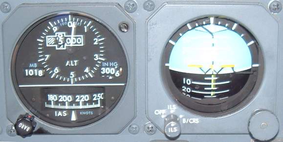
The standby airspeed indicator & altimeter uses aux
pitot & alternate static sources and no
ADC/ADIRU’s.
The Integrated Standby Flight Display started to appear in 2003 to replace
the mechanical standby artificial horizon and ASI/Altimeter. Personally I find
the new ASI & Altimeter much easier to read but the ILS more difficult.
The + - buttons are just brightness controls.
The ISFD also
sends inertial data to the FCCs which use the data during CAT IIIB
approaches, landings and go-around.
Interestingly the ISFD
cannot be switched off from the flightdeck - even by pulling the ISFD c/b on
the p18 panel. It has its own dedicated battery and the ISFD c/b only
removes power from the battery charger, so let us hope that one does not start to smoke
in-flight! The battery will give 150 mins of power.
Finally, if all else fails there is a standby magnetic compass!
The FDR is located above the ceiling above the rear galley. Despite its common name of a "Black Box" it is not black but high visability orange.
There have
been several different models of FDR in the life of the 737 which can
collect anything from 30 minutes to hundreds of hours of data of 8 to hundreds of
parameters.
The FDR is located above the rear galley
Early FDR's, as fitted to 737-200's, comprised metal scribes which etched
their data into a 150ft long roll of metal foil. These would last about
300hrs but only recorded vertical acceleration, heading, IAS and altitude,
plus binary traces such as date, flight number and time of R/T
transmissions. A gauge on the panel (see below) shows the recording hours
remaining before the foil spool needs replacing.
Later second generation Digital FDR's (late 200's & early classics) record onto a 1/4-inch wide,
450 feet long magnetic tape. These can record up to 25 hr of data.
The newest Solid State FDR's (later classics, NG's & MAX) record 25 hours of data onto memory chips.
737-200 FDR panel
The protective
casing includes an inner aluminium cover, isothermal protection shield, an
outer stainless steel casing and an exterior stainless steel dust cover.
This enables it to withstand a crush force of 20,000 pounds per axis, and
provides impact protection of 1000 g's for 5 msec. It is protected from heat
by an isothermal insulation which maintains the inner chamber at a safe
temperature.
The FDR of the 737-NG is similar to that described above but can
withstand 3400 g's of impact, 20,000ft depth of water and temperatures of
1,100C for 30mins.
FDRs and CVRs have an underwater location device that, when activated by water, emit an ultrasonic pulse at 37.5 kHz every second for a duration of at least 30 days.
The FDR starts recording as soon as the first engine N2 exceeds 50% and will remain recording whislt either engine is running or the aircraft is in the air.
For information on the Cockpit Voice Recorder (CVR) click here
This video covers the CVR, FDR, ELT, LF-ULB, DFDAU and QAR on the 737. It also discusses the use of ACMS data within an airline and how hard landings are measured.
EFB is becoming the latest “must-have” device in the cockpit. They have
the ability to do the following tasks:
Calculate take-off or landing performance.
Calculate weight & balance.
Contain the aircraft technical log.
Store navigation charts & plates.
Store company manuals, FCOMs, crew notices, etc.
Retrieve & display weather.
Display checklists.
Display on-board video surveillance cameras.
The advantages to crew are the accuracy of the data and ease of use. The
advantages to the airlines are the cost benefits of a less paper cockpit and
real time data transfer.
There are three classes of EFB:
Class 1: Fully portable. Eg a laptop.
Class 2: Portable but connected to the aircraft during normal
operations. Eg tablet & docking station.
The Boeing Business Jet stands at a crossroads in avionics
technology—exploiting all the flight deck systems available to airlines
operating the 737, while serving as a showcase for advanced bizjet avionics
that air carriers may one day want.
The BBJ often serves as a pathfinder for the latest systems that
eventually could find their way onto commercial 737 flight decks.
Improved situational awareness is a case in point. Gulfstream, for
example, pioneered the use of enhanced vision systems (EVS) with a
forward-looking infrared (Flir) camera on large-cabin bizjets. This allows
pilots to look through a head-up display (HUD) to see Flir imagery of a
runway at night and in smoke, haze, rain and snow (but not in large-droplet
fog).
The enhanced vision capability is more than just a safety feature. The
FAA allows business jet pilots to use EVS images to fly as low as 100 ft.
AGL (instead of 200 ft. during a Category-1 approach) before having to see
the runway visually. Currently, airline pilots can’t do this. However, the
FAA and the European Aviation Safety Agency are considering changing this
rule to allow airlines to descend to 100 ft. with EVS, according to several
avionics company officials. This could happen as early as next year.
There’s already substantial airline interest in enhanced vision, says
Steve Taylor, the BBJ chief pilot. “I’ll wager if the FAA grants that OK to
the airlines [for 100 ft. ], they will be beating on our door,” he adds.
Rockwell Collins is working with Boeing on the EVS program. And Max-Viz
Inc., of Portland, Ore., is developing a multisensor, uncooled camera to
meet a Rockwell Collins specification. It has both a short-wave and a
long-wave infrared sensor and a visible-light camera in one unit.
The BBJ also will have a new version of the Rockwell Collins HGS-4000,
called the -4000E. This modification of the head-up guidance system includes
new hardware and software to allow the display of video imagery from the
Flir camera. The BBJ has head-up guidance for the pilot as a standard
feature, while the system is optional on the 737NG. Taylor says every
avionics system that’s optional on the airline version of the 737 is
standard on the BBJ.
Meanwhile, Rockwell Collins just began flight testing the BBJ enhanced
vision system on its Sabreliner testbed, and the EVS will be flown on a
customer’s BBJ during the winter. Certification should occur in mid-2008.
Should airlines become more interested in having it on a 737NG, it wouldn’t
take much additional work to commercialize the system, says Taylor. “The
aircraft certification rules are the same—Part 25,” he notes, so the
certification effort on the BBJ should transfer easily to the 737NG.
The plan is to display the EVS imagery not only on the HGS for the pilot
but also on one of the six Honeywell cockpit displays (the one on the
pedestal so the copilot also can see the Flir imagery).
Taylor notes that head-up guidance systems made their first entry at
Boeing on the BBJ and then moved to the commercial aircraft production line.
But earlier, HUDs were already flying on existing airline aircraft because
carriers such as Southwest and Alaska Airlines had installed them as
retrofit items.
However, avionics is not the only area where technical innovation started
in the BBJ program and was then incorporated on commercial transports.
Winglets, a key fuel-saving device, is an example. “In a sense, we are a
Skunk Works for commercial airplanes,” says Taylor.
As for the next big thing in business aviation, it will likely be another
situational-awareness advance called synthetic vision. A 3D digital map of
the terrain and obstacles ahead of the aircraft will be shown to the pilots
of Gulfstream business jets soon, thanks to Honeywell. Rockwell Collins is
developing a similar system for Bombardier. This Aviation Week & Space
Technology pilot saw a Honeywell prototype last year on a Cessna Citation V
(AW&ST Oct. 16, 2006, p. 66). Our night flight passed over the Phoenix area
where I attended U.S. Air Force pilot training in the early 1970s. The view
out the windscreen was often pitch-black, with mountains below shrouded in
darkness. But I could see the “synthetic” terrain on the primary flight
display created from a database that portrayed the scene ahead as if it were
broad daylight. In 1971, a T-38 crashed into a nearby mountain in the era
before synthetic vision.
A key question is, How long will it take for the huge safety advance of
synthetic vision to show up on commercial flight decks? Since I no longer
fly T-38s, I have to travel economy class on narrow- or wide-body jets. If
airline pilots had EVS and SVS, I would feel safer as a passenger flying
into airports surrounded by high terrain. But as with EVS and the possible
FAA rule change on 100 ft., SVS will need a business case to earn its way
onto an airline flight deck. At the moment, it’s not clear what that
rationale will be.
Taylor says technology specialists at Boeing are looking at synthetic
vision, and he believes its adaptation will follow a path similar to the one
for enhanced vision. In the business jet market, “the customer base is much
more interested in technology and willing to pay for it,” he notes.
Another way the BBJ benefits from 737 avionics is that the standard-fit
radar is an airline-class system—Rockwell Collins’ multiscan WXR2100, which
is flying with 100 airlines. It’s a more capable system than many of the
radars currently installed in business jets. Keith Stover, Rockwell Collins’
radar marketing manager, says the main benefit for BBJ pilots is automatic
adjustment of the radar as well as ground-clutter suppression.
In September, Rockwell Collins said it will provide a multiscan radar for
bizjets to accommodate the smaller antenna sizes they need of 12 and 18 in.
So this is an example of airline-class avionics technology flowing to
business aviation by way of the BBJ flight deck. The airline version, which
is already standard on the BBJ, has a 28-in. antenna and includes wind shear
protection.
Last summer, I flew on a BBJ over the North Atlantic. During the flight,
Rockwell Collins radar engineers were perfecting new software to allow the
multiscan radar to improve its automatic detection of storms in a particular
region (AW&ST July 9, p. 44). This new geographic-discrimination software
will be available soon on the BBJ.
Additional fuel tanks are added after the aircraft leaves the factory and
goes to DeCrane Aerospace at Sussex County Airport in Georgetown, Del. This
is also where the new enhanced vision system will be fitted.
 Flight Instruments


 The NG's have 6 Display Units (DU's), these display the flight
instruments; navigation, engine and some system displays. They are
controlled by 2 computers - Display Electronics Units (DEU's).
Normally DEU 1 controls the Captains and the
The NG's have 6 Display Units (DU's), these display the flight
instruments; navigation, engine and some system displays. They are
controlled by 2 computers - Display Electronics Units (DEU's).
Normally DEU 1 controls the Captains and the 

 One of the many customer PFD options is an analogue/digital angle of attack
display. The red line is the angle for stick shaker activation, the green
band is the range of approach AoA.
One of the many customer PFD options is an analogue/digital angle of attack
display. The red line is the angle for stick shaker activation, the green
band is the range of approach AoA.


 EFB is becoming the latest “must-have” device in the cockpit. They have
the ability to do the following tasks:
EFB is becoming the latest “must-have” device in the cockpit. They have
the ability to do the following tasks: