|

The hydraulic pump panel -1/200
The 737-1/200 had system A powered by the two Engine Driven Pumps (EDP's) and
system B powered by the two Electric Motor Driven Pumps (EMDP's). There is also
a ground interconnect switch to allow system A to be powered when the engines
are shut down.

The hydraulic pump panel -300 onwards
From the 737-300 onwards each hydraulic system had both an EDP and an EMDP
for greater redundancy in the event of an engine or generator failure.
The EDP’s are much more powerful, having a hydraulic flow rate of 22gpm (Classics) / 37gpm (NG). The EMDP’s only produce 6gpm. The standby system output is even less at 3gpm.
Note that the EDP’s do not have an OVERHEAT light. This is because they are mechanically (not electrically) driven and have very little heat rise so there is no need for an overheat warning. Note also that the EDPs are always working when the engine is turning, they can not be disconnected or switched off. Switching an EDP off leaves the pump running but opens a pressure relief bypass valve to take the fluid away from the pump.
To see the hydraulic systems (pumps, reservoirs, gauges
etc) see wheel-well fwd
|
Services Supplied |
|
System A |
System B |
Standby |
|
A/P "A" |
A/P "B" |
|
|
Ailerons |
Ailerons |
|
|
Rudder |
Rudder |
Rudder |
|
Yaw damper |
Standby yaw damper (as installed) |
|
Elev & Elev feel |
Elev & Elev feel |
|
|
Inboard flight spoiler |
Outboard flight spoiler |
|
|
Ground spoilers |
|
|
|
L/E flaps & slats |
L/E flaps & slats (for extension only)
|
|
T/E flaps |
|
|
PTU for autoslats |
Autoslats |
|
|
No1 thrust reverser |
No2 thrust reverser |
Nos 1 & 2 thrust reversers (slow) |
|
Nose wheel steering |
Alt nose wheel steering |
|
|
Alternate brakes (man only) |
Normal (auto & man) brakes |
|
|
Landing gear |
Landing gear transfer unit (retraction only) |
|
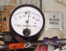
Hydraulic System B Reservoir Pressure Gauge
The hydraulic reservoirs are pressurised from the pneumatic manifold to ensure a positive flow of fluid reaches the pumps. A from the left manifold and B from the right (see wheel-well
fwd). The latest 737's (mid 2003 onwards) have had their hydraulic reservoir
pressurisation system extensively modified to fix two in-service problems 1)
hydraulic vapours in the flight deck caused by hydraulic fluid leaking up
the reservoir pressurisation line back to the pneumatic manifold giving
hydraulic fumes in the air-conditioning and 2)
pump low pressure during a very long flight in a cold soaked aircraft. The
latter is due to water trapped in the reservoir pressurisation system freezing
blocking reservoir bleed air supply. Aircraft which have been modified (SB
737-29-1106) are recognised by only having one reservoir pressure gauge in the
wheel well.
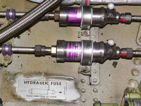
Hydraulic Fuses
Also in the wheel well can be seen the
hydraulic fuses. These are essentially spring-loaded shuttle valves which close the hydraulic
line if they detect a sudden increase in flow such as a burst downstream,
thereby preserving hydraulic fluid for the rest of the services. Hydraulic fuses
are fitted to the brake system, L/E flap/slat extend/retract lines, nose gear
extend/retract lines and the thrust reverser pressure and return lines.
Above schematic courtesy of Leon Van Der Linde. For a
more detailed hydraulic
schematic diagram, click here.

737-3/400 Hydraulic Gauges
On pre-EIS aircraft (before 1988) the hydraulic gauges were similar to the
737-200. There are now separate quantity gauges since the reservoirs are not
interconnected and the markings have been simplified. There is now just a single
brake pressure gauge showing the normal brake pressure from system B.

737-200 Hydraulic Gauges.
Notice that there is only a system A quantity gauge, this is because on the
737-1/200 system B is filled from system A reservoir. System B quantity is
monitored by the amber "B LOW QUANTITY" light above. The hydraulic brake
pressure gauge has two needles because system A operates the inboard brakes and
system B the outboard brakes, each has an accumulator.
This table shows the nominal quantities at different levels in the reservoirs
| |
Aircraft Series |
Originals |
Classics |
NG's |
| System |
|
Gauges |
EIS |
Upper CDU |
| A |
Full level |
3.6 USG |
100% |
100% (5.7Gal / 21.6Ltrs) |
| Refill |
2.35 USG |
88% |
76% |
| EDP Standpipe |
? |
22% |
20% |
| EMDP Standpipe |
N/A |
0% |
0% |
| B |
Full level |
Full |
100% |
100% (8.2Gal / 31.1Ltrs) |
| Refill |
3/4 |
88% |
76% |
| Fill & balance line (to standby reservoir) |
? |
64% |
72% |
| EDP Standpipe |
N/A |
40% |
0% |
| EMDP Standpipe |
? |
11% |
0% |
Eg. If you are in say a 737-300 and you notice to System B hydraulic quantity
drop to 64%, then from the table above, you may suspect a leak in the balance
line or standby reservoir.
Note: Refill figure valid only when airplane is on ground with both engines shutdown or after landing with flaps up during taxi-in.
The hydraulic reservoirs can be filled from the ground service connection
point on the forward wall of the stbd wheel well.

Hydraulic ground service connection
Normal hydraulic pressure is 3000 psi
Minimum hydraulic pressure is 2800 psi
Maximum hydraulic pressure is 3500 psi
Normal brake accumulator precharge is 1000 psi
NB The alternate flap system will extend (but not retract) LE devices with standby hydraulic power. It will also extend or retract TE flaps with an electric drive motor but there is no asymmetry protection for this.
LGTU makes Hyd B pressure available for gear retraction when Engine No1 falls below 50% N2
Methods for Transfer of Hydraulic Fluid
It should go without saying that if a hydraulic system is low on quantity
then you should top up that system with fresh fluid (and find out why it was
low!) to avoid cross contamination. However if you really want to move fluid
from one system to another here is how to do it.
A to B (Ref 737NG-FTD-29-16003)
- With wheel chocks in place, turn off both the system A and system B EMDP's.
- Turn the system A EMDP on.
- Set the parking brake.
- Turn the system B EMDP on.
- Release the parking brake.
- Turn both the system A and system B EMDP's off.
- Repeat this procedure if needed
Boeing would like to note that EMDP's can be overheated if this procedure is used too many times in a short duration. We recommend that EMDP's be operated intermittently a maximum of five times in a five minute period (with a 30 second wait time between each stop and start of the pump). After completing five iterations of the procedure mentioned above, the pumps should either be run continuously for five minutes after the fifth cycle (while monitoring the overheat warning lights) or turn both pumps off and let them cool for more than 30 minutes.
Each iteration of the procedure above will result in 15-20 cubic inches of fluid transfer from system A to system B. As such, the aforementioned procedure is not recommended for transferring larger amounts of fluid between hydraulic systems. Boeing recommends servicing the hydraulic reservoirs per AMM Task 12-12-00-610-801 when possible.
B to A (4% transfer per cycle)
- Ensure area around No1 thrust reverser is clear.
- Switch both EMDP's OFF
- Switch either FLT CONTROL to SBY RUD.
- Select No1 thrust reverser OUT (uses standby hyd sys)
- Switch FLT CONTROL to ON.
- Switch Hyd Sys A EMDP ON.
- Stow No 1 thrust reverser (using sys A)
Click here to see a detailed hydraulic
schematic diagram.
|  Hydraulics

