Back to home pageMain Wheel-well Comparison

Home > Aircraft Systems > Wheel-well > Comparison

Contents

Illustrated technical information covering Vol 2 Over 800 multi-choice systems questions Study notes and technical information Close up photos of internal and external components A compilation of links to major 737 news stories with a downloadable archive Illustrated history and description of all variants of 737 Detailed tech specs of every series of 737 Databases and reports of all the major 737 accidents & incidents General flightdeck views of each generation of 737's Description & news reports of Advanced Blended Winglets Press reports of orders and deliveries Articles from the press and official sources following the troubled history of the rudder PCU Details about 737 production methods A compilation of links to other sites with useful 737 content Get the book of the website A quick concise overview of the pages on this site

Contents

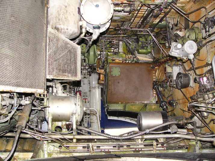
The following photos show the main wheel-well looking starboard on each of the three generations of 737.

See more details about the book

All of the information, photographs & schematics from this website and much more is now available in a 370 page, 8.5" x 11" book available here.

Updated 23 May 10

737-200

This photo shows the wheel well of a 1969 vintage 737-200. The majority of components and locations are unchanged to the NG series in production today.

The screens on the forward wall are to protect vital components from gravel damage thrown up by the tyres as this aircraft was delivered with the unpaved strip kit.

737-Classic

At first glance the wheel-well of the classic appears the same as original 737's.

Some differences are the larger hydraulic reservoirs and the standby reservoir is now in the centre of the keel beam. The is now a single, larger brake accumulator.

737-NG

One significant difference is the absence of the gear downlock viewer, compare this to the overhead photo to see the difference

The standby hydraulic reservoir has now changed shape and moved further aft to the aft wall. The standby hydraulic pump is now under an access panel aft of the RH wheel-well.

The main landing gear is inclined slightly backwards.

This site has had visitors to date.